Critical Equipment Monitoring
Project Information
Contents
Authors
- Rio Akbar
- Calvin Nguyen
- Erik Stefan
- James Tarrant
- Dylan Turner
1. Introduction
1.1 Purpose
The purpose of this document is to describe the end-to-end design of the radio repeater remote monitoring system. This is intended to provide information for troubleshooting the existing system, or to build on the design to add additional functionality.
1.2 Background
The WA State Emergency Service (SES) provides a wide range of volunteer services during natural disaster or emergency situations, to help the community cope and recover from the impacts. The Communications Support Unit (CSU) is a function of the SES that provides vital radio and data links to restore and maintain safety critical communications. The CSU uses radio repeaters in remote or hilly terrain to extend two-way radio communications between Users that are otherwise out of line-of-site propagation range, as shown in Figure 1.
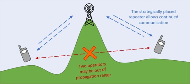
The repeater set-up is mobile, temporary, and typically independently powered. Once the Field Operative has installed the equipment, it will be left online and unmanned. Therefore, the Operators are only aware of an issue with the repeater (such as loss of power) once the quality of communication degrades. It may be several hours before the Field Operative can reach the repeater to restore functionality.
1.3 Initiative
It is an initiative of the CSU to improve availability of deployed repeaters by obtaining advanced warning of potential issues. The status of key components such as normal and backup power supplies should be monitored. The Operator should be aware of changes in state, with sufficient time to take remedial action.
The functionality in this Design and Testing Document, in particular the monitoring of the normal and back-up power supplies, are to support this initiative.
1.4 Previous System
The CSU operates a range of radio repeaters of varying make and model. They are typically powered via 240VAC from a generator, or a grid connected outlet. This is the “Normal Supply” shown in Figure 2.
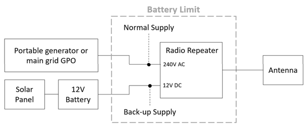
If the normal supply fails, such as failure of the generator, the repeater will automatically changeover to a 12VDC supply. This is the “Back-up Supply” shown in Figure 2, and is usually provided by a 12V battery and solar panel.
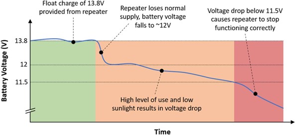
When the normal supply is unavailable, the back-up supply may only provide power for several hours. The actual duration relies on the sunlight received by the solar panel and the level of usage of the repeater. Figure 3 illustrates the effect on battery voltage when normal supply is lost, and the threshold at which the repeater functionality deteriorates. The existing system does not incorporate remote monitoring functionality. Therefore, there is no advanced warning of repeater performance degradation. The following sections describe the system designed and implemented to provide the remote monitoring improvement.
2. System Architecture
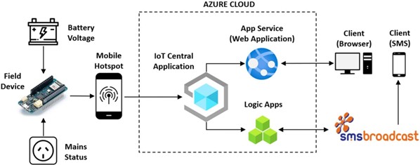
Figure 4 shows the new architecture implemented by the project team. The field device samples the battery voltage and mains status. This telemetry is sent to the IoT Central service. IoT Central provides the API used by the web application (hosted in Azure App Services) to read and display the telemetry. IoT Central will also initiate the SMS notifications, via Azure Logic Apps and SMS Broadcast, to notify the Client of issues with the repeater power supplies.
3. Hardware
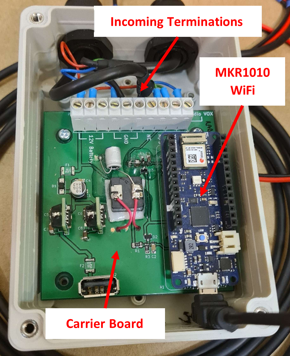
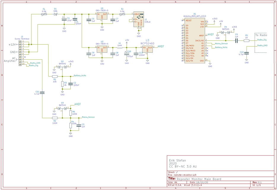
The hardware consists of an Arduino MKR WIFI 1010 module, a carrier board into which the Arduino is inserted, and a sensor which is placed near the mains or generator power cord going into the repeater to detect 50Hz 240V AC. The Arduino module is responsible for the analysis and reporting of data to the IoT Central Application. It collects data from the 12V battery line and the mains/generator line and, using its onboard Wi-Fi module, reports this to the website as shown in Section 2.
The carrier board supplies power to the system from the 12V battery, stepping it down to 5V through a switch-mode power supply. It also provides a means of connecting the mains sensor output to the Arduino through screw terminals, protection circuitry to prevent damage to the device from incorrect connections, and a USB Type A charging port which can supply power to a mobile hotspot or mobile phone.
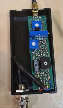
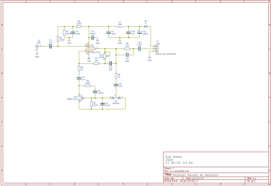
The mains sensor amplifies and low-pass-filters any signal picked up by the sensor wire. This amplified signal is then sent to the Arduino for analysis. The sensor is designed to be placed as close to the cable-to-be-monitored as possible, as this limits the amount of unwanted noise which may be picked up by a longer sensor wire. It takes power directly from the 12V battery line (bypassing the carrier board’s power supply).
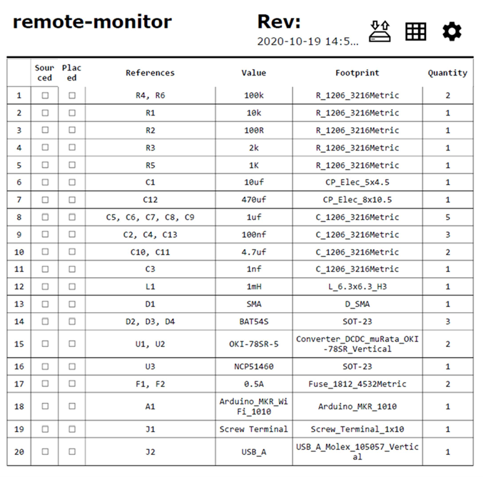
The final device is shown in Figure 5 and Figure 6. Refer to Appendix A for a hardware schematic, and Appendix B for the corresponding Bill of Materials.
The latest firmware for the device can be found at the following git repository: https://github.com/erik6K/remote-monitor/tree/master/firmware
The functionality of the firmware is too extensive to describe in detail in this design document. Therefore, the logic flow diagram shown in Appendix C has been produced to graphically describe the functionality at a high-level.
During the “Analyse” state the device takes a burst of 1024 samples of the signal picked up by the mains sensor (AC amplifier) and performs a Fast Fourier Transform (FFT) on the data in order to find the relative magnitudes of different frequencies present. It then checks the magnitude of the 50Hz frequency against the noise floor to determine whether mains voltage is present.
4. IoT Central Application
The IoT Central Application is used as the gateway to bring the device telemetry into the Azure Cloud. The application performs the key functions described in the following sections.
4.1 MQTT Client
MQTT is the Messaging Querying Telemetry Transport protocol. This is a lightweight publish and subscribe protocol, preferred in internet of things applications such as this project. The field device is programmed to periodically publish its telemetry over MQTT to the IoT Central Application. IoT Central is subscribed to these topics and will store the data to be displayed on the dashboard or retrieved via the REST API.
4.2 REST API
The IoT Central Application provides a REST API that allows other applications to perform operations that are usually performed from within the IoT Central GUI. This project uses the following APIs within the web application:
- Devices - List: Retrieve the list of devices currently deployed in IoT Central
- Devices - Get Component Telemetry Value: Retrieves the most recent mains status and battery voltage, to be displayed on the web application
- Devices - Get Cloud Properties: Retrieves whether notifications are currently enabled or disabled for each device and telemetry type.
- Devices - Update Cloud Properties: Updates whether notifications should be enabled/disabled for a particular device telemetry type.
For a full list of REST APIs refer to: https://docs.microsoft.com/en-us/rest/api/iotcentral/
4.3 Dashboards
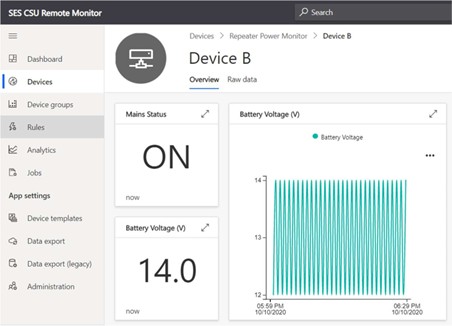
The dashboards provide a secondary way to view device telemetry, in addition to the web application (Refer section 5). An example of this dashboard is shown in Figure 7.
4.4 Device Templates
A template of the remote monitoring device has been pre-configured in the cloud. New devices can be provisioned using this template, with minimal configuration required.
4.5 Rules
Rules are used within IoT Central to trigger events when certain conditions are met. These rules have been used to implement the SMS notification functionality described in Section 6.
5. Web Application
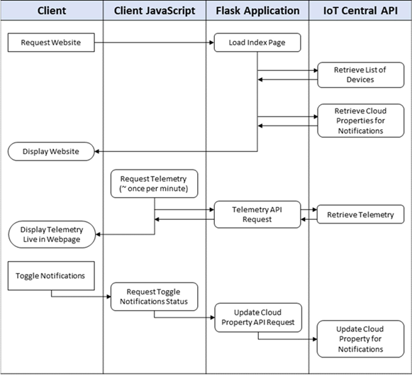
A web application has been developed to provide the functionality described in Figure 8. Its primary functions are to view the devices, most recent telemetry, and manage SMS notifications.
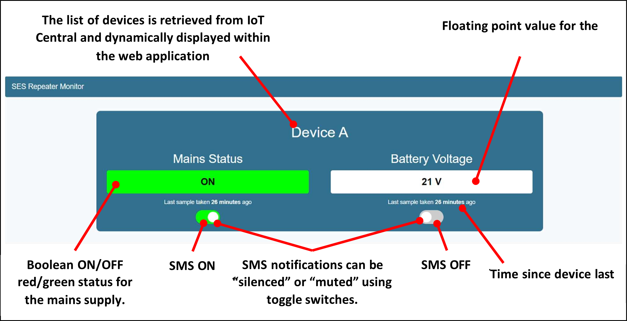
The application is written in Python, using Flask as the web application framework. To avoid the need to update the website when deploying new devices, templating is used to dynamically create the HTML by pulling the data straight from IoT Central. Jinja2 is used as the templating language. The high-level design of the web application has been described in the logic flow diagram in Figure 9.
The full code is contained in the following git repository. Please contact a member of the team for access, if required: https://github.com/tarrantja/remote-monitor-web
The application is hosted using Azure App Services, using Gunicorn as the internal Web Server Gateway Interface (WSGI) HTTP server: https://repeater-monitor.azurewebsites.net/
6. Notifications
Since the team was on track to complete the core functionality described in the Scope of Work, attention began to turn to possible stretch goals and additional features. One of these was a method for notifying an operator (via SMS or Email) of an issue, rather than needing to periodically check the web application.
6.1 IoT Central Rules
The IoT Central application allows setting of ‘rules’ to trigger a subsequent action when certain conditions are met. The two rules shown in Table 1 were added to implement the notification functionality.
| Trigger | Filter | Action |
|---|---|---|
| Mains Status OFF | If ‘Cloud Mains Status Notification’ property is set to ‘OFF’, do not trigger. | Trigger Logic App ‘remote-monitor-notifications’. Refer Section 6.2. |
| Battery Voltage < 11.9V | If ‘Cloud Battery Voltage Notification’ property is set to ‘OFF’, do not trigger. | Trigger Logic App ‘remote-monitor-notifications-battery’. Refer Section 6.2. |
6.2 Logic Apps and SMS Broadcast
The project team then created two simple Logic Apps within Azure, one to trigger SMS notifications on mains failure, and the other to trigger SMS notifications on low battery voltage. Each logic app has a “trigger” which comes from the IoT Central Application when the rules in Table 1 are satisfied. The subsequent “action” is to initiate a HTTPS POST request to the SMS Broadcast API. SMS Broadcast has been selected at the request of the Client, who have an existing account with credits to cover the cost of the SMS notifications.
6.3 Notification Silencing
The rules will be triggered whenever telemetry is received that matches the relevant criteria. To prevent flooding of SMS alerts, each telemetry type (battery and mains) has an associated ‘Cloud Telemetry Status Notification’ property assigned. When this property is set to ‘OFF’, the notifications would be filtered out, as stated in Table 1. This filter can be toggled on and off within the web application, as shown previously in Figure 8.
7. Security
To manage security, a large cloud service provider, like Azure, was preferred because of their built-in cyber security controls. Table 2 shows the possible system security threats, and controls to manage.
| Threat | Consequence | Control |
|---|---|---|
| Access to the device via the internet | Damage to device or connected equipment | Device is publishing-only and does not receive commands/data. |
| Access to IoT Central via the internet | Ability to add/change/delete all devices and associated data. | Devices connect securely to IoT Central using a Secure Access Token. Applications connect securely using a unique access key. |
| Unauthorized access to the IoT Central Portal | As above | Authentication and access authorization to IoT Central is fully managed by Microsoft. Permissions can be set within the application to control access if required. |
| Loss or theft of the device | The secret credentials within the firmware can also be stolen, and the firmware can be changed. | If lost or stolen, recommend:
|
| Malicious access to web application source code | Change, delete or deface the web application | Changes pushed to the master branch of the web application git repository will be automatically published. Therefore, access to the git repository should only be provided to trusted parties. App Services can be used to de-link the git repository if required. Refer to User Manual - disaster recovery for web application. |
| Unauthorised access to web application. | Disable or enable SMS notifications. | Access to the web application shall be restricted to users within the Client’s applicable Azure Active Directory. |
8. IP Exploitation Model
8.1 Distribution Model
As agreed in the Scope of Work, the project has been modelled via a creative commons distributing rights model. The Creative Commons (CC) license enables free distribution of an otherwise copyrighted "work". The Team has licensed the project deliverables as Creative Commons 3.0 Non-Commercial Australian License. In essence, the Team has given the Client the right to share, use, and build upon what the Team have created, in line with the conditions below.
8.2 Client Rights
- SHARE - copy and redistribute the material in any medium or format
- ADAPT - remix, transform, and build upon the material The Client must adhere to the following terms:
- ATTRIBUTION - Give appropriate credit, provide a link to the license, and indicate if changes were made.
- NON-COMMERCIAL - The Client may not use the material for commercial purposes.
- NO ADDITIONAL RESTRICTIONS - The Client may not apply legal terms or technological measures that legally restrict others from doing anything the license permits.
9. Cost
9.1 Ongoing Monthly Costs
Each cloud service represents an ongoing monthly cost. The monthly cost, at point of handover, is shown in Table 3. This will change as more devices are deployed. Before adding more devices is it recommended to refer to the Azure pricing overview information for each service.
| Service | Tier | $/month |
|---|---|---|
| Azure App Service Plan | Free | $0/month |
| Azure Logic Apps | Usage based. $0.000218 per SMS | ~$0/month |
| Azure IoT Central Application | Standard Tier 1 - First 2 devices free | ~$0/month |
| SMS Broadcast | 3.7c per SMS | $3.70/month for 100 SMS |
| TOTAL | <$4/month |
9.2 Device Cost
Each device represents a once-off cost. Refer to the bill of materials in Appendix B for a list of parts. The approximate cost for all equipment for a new device is $90-$110, depending on suppliers.
10. User Acceptance Tests
This section documents the user acceptance tests executed to prove the project design (described in this document) has met all requirements laid out at the beginning of the project. A summary of all tests is provided in Table 4.
| Story | Core/Additional | Test Pass/Fail |
|---|---|---|
| Story 1.1 Powering Device | Core | PASS |
| Story 1.2 Powering Mobile Hotspot | Additional | PASS |
| Story 2.1 Detects Main Voltage | Core | PASS |
| Story 2.2 Detects Battery Voltage | Core | PASS |
| Story 3.1 View Web Page | Core | PASS |
| Story 3.2 View Live Data | Core | PASS |
| Story 4.1 Reporting of Data Via Radio | Additional | NOT TESTED |
| Story 5.1 Receiving Notifications | Additional | PASS |
| Story 5.2 Silencing Notifications | Additional | PASS |
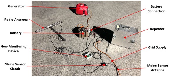
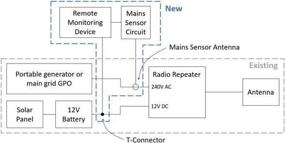
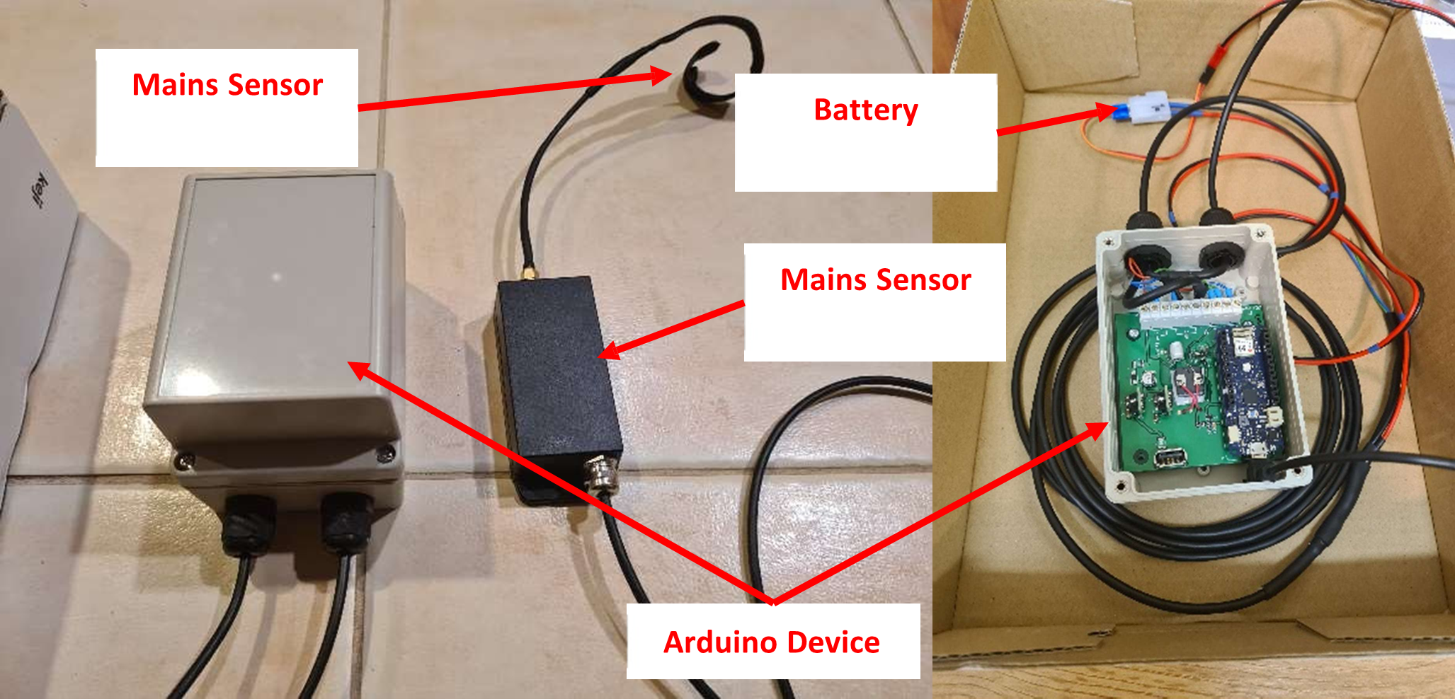
Figure 10 and Figure 11 show the equipment used during the tests. Not all equipment was required for each test.
10.1 STORY 1.1 - POWERING DEVICE
10.1.1 Story
As a Field Operative, I want to power the device using the existing battery connector, so that it is standardised across batteries.
10.1.2 Test and Results
| Step | Action | Result |
|---|---|---|
| 1. | Connect T-Connector to battery connector | OK |
| 2. | Connect device to T-connector | OK |
| 3. | Confirmed device power indicator LED illuminates | CONFIRMED |
10.2 [STRETCH] STORY 1.2 - POWER MOBILE HOTSPOT
10.2.1 Story
As an Operator, I want a way of powering a mobile hotspot or mobile phone from the device, so I do not need to rely on the hotspot/mobile internal battery.
10.2.2 Test and Results
| Step | Action | Result |
|---|---|---|
| 1. | Connect the device to the 12V DC supply | OK |
| 2. | Connect the mobile phone to the USB A charging port provided on the device | OK |
| 3. | Confirm the mobile charges. | CONFIRMED |
10.3 STORY 2.1 - DETECTS MAINS VOLTAGE
10.3.1 Story
As a Field Operative, I want a device which I can interface with my repeater’s main power source in an isolated fashion, so that it can detect the presence of power.
10.3.2 Test and Results
The first test was completed with the repeater powered from the mains generator. The results are shown in Table 7.
| Step | Action | Result |
|---|---|---|
| 1. | Wrap sensor onto 240VAC cable | OK |
| 2. | Ensure generator is running, cable plugged in, and connected to repeater | OK |
| 3. | Power on device | OK |
| 4. | Confirm indication LED lights up to show presence of 50Hz mains | CONFIRMED |
| 5. | Unplug generator cable and confirm LED turns off | CONFIRMED |
The test was repeated using a normal grid-connected 240V mains outlet. The results are shown in Table 8.
| Step | Action | Result |
|---|---|---|
| 1. | Connect the repeater to a 240VAC general purpose outlet | OK |
| 2. | Wrap the antenna around the 240VAC cable | OK |
| 3. | Power on device | OK |
| 4. | Turn outlet on and confirm LED indicator shows presence of voltage | CONFIRMED |
| 5. | Turn outlet off and confirm LED indicator turns off | CONFIRMED |
10.4 STORY 2.2 - DETECT BATTERY VOLTAGE
10.4.1 Story
As a Field Technician, I want a device which can interface with the backup 12V battery using the existing connector, so that it can measure its voltage.
10.4.2 Test and Results
| Step | Action | Result |
|---|---|---|
| 1. | Connect the device to the battery using the T-connector | OK |
| 2. | Connect the device to the serial monitor to monitor output | OK |
| 3. | Compare the voltage level on the serial monitor to the voltage read from a reliable multimeter, and confirm they are within +/- 0.1V. | CONFIRMED |
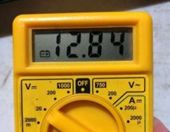
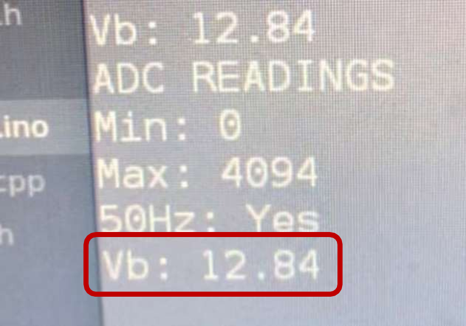
Figure 12: (a) Multimeter Reading from Battery (b) Reading from Device
10.5 STORY 3.1 - VIEW WEB PAGE
10.5.1 Story
As an Operator, I want to go to a web page and see an on/off status for the main repeater 240VAC supply and a battery voltage, so that I have a convenient user interface for tracking repeaters.
10.5.2 Test and Results
| Step | Action | Result |
|---|---|---|
| 1. | Open the Web Application | OK |
| 2. | Confirm the list of deployed devices can be viewed. | CONFIRMED |
| 3. | Confirm there are values displayed for the device telemetry. | CONFIRMED |
| 4. | [Stretch] Confirm the duration since data was last report is displayed. | CONFIRMED |
| 5. | [Stretch] Open the application on a mobile device and ensure layout is optimised for mobile. | CONFIRMED |
10.6 STORY 3.2 - VIEW LIVE DATA
10.6.1 Story
As an Operator, I want the web page to be updated with field data in real time, so I can have the most up to date information for decision making.
10.6.2 Test and Results
| Step | Action | Result |
|---|---|---|
| 1. | Open the Web Application | OK |
| 2. | Power the battery via the device | OK |
| 3. | Confirm, via the Serial monitor, that the device has connected to the WiFi hotspot | CONFIRMED |
| 4. | Confirm, via the Serial monitor, that the device has connected to the MQTT Client | CONFIRMED |
| 5. | Change the battery voltage and confirm the value updates live within the Web Application | CONFIRMED |
10.7 [STRETCH] STORY 4.1 - REPORTING OF DATA VIA RADIO
10.7.1 Story
As an Operator, I want to be informed of when the repeater’s main and back-up power source fails by radio, so that I can be aware of impending repeater failure.
10.7.2 Test and Results
To ensure core functionality could be implemented to a high level of quality, and to focus on higher priority stretch targets (refer stories 2.1, 5.1 and 5.2) this stretch target was left partially completed. Therefore, this story has not been tested. Logic has been built into the firmware to allow this functionality to be added in a future project. Refer to Appendix C for more details.
10.8 [STRETCH] STORY 5.1 - RECEIVING NOTIFICATIONS
10.8.1 Story
As an operator I want to be immediately notified of a mains voltage failure or low battery level, so I can act.
10.8.2 Test and Results
| Step | Action | Result |
|---|---|---|
| 1. | Connect the device to the battery and mains supply | OK |
| 2. | Turn the mains supply off | OK |
| 3. | Confirm an SMS alert is received describing the event | CONFIRMED |
| 4. | Reduce the battery voltage below 11.9V | OK |
| 5. | Confirm an SMS alert is received describing the event | CONFIRMED |
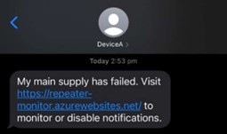
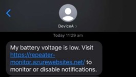
Figure 13: (a) Mains Failure SMS (b) Battery Failure SMS
10.9 [STRETCH] STORY 5.2 - SILENCING NOTIFICATIONS
10.9.1 Story
As an operator I want the ability to disable notifications of the main voltage status, so I can deploy a repeater without a generator and not become flooded with irrelevant notifications, or prevent alarms once I am already aware of an issue.
10.9.2 Test and Results
| Step | Action | Result |
|---|---|---|
| 1. | Repeat steps 1-5 from Table 12. | OK |
| 2. | On the web application, toggle the notifications for the Mains Status to OFF. | OK |
| 3. | Confirm the notifications related to the mains status are no longer received. | CONFIRMED |
| 4. | On the web application, toggle the notifications for the Battery Voltage to OFF. | OK |
| 5. | Confirm the notifications related to the battery voltage are no longer received. | CONFIRMED |
11 HANDOVER
A handover is a process, not a date such as a unit deadline. The purpose of this section is to describe how the project will be handed over to the Client, and what support or interactions may be expected between the Client and Team following the completion of the project.
11.1 DOCUMENTATION
The knowledge needed to sustain the system is contained within the Installation and Operation Manual. This document captures all activities for the intended use of the device. Additionally, it contains instructions for changing key system parameters. The knowledge to understand and further develop the system is contained within this Design and Testing Document, and the linked code repositories.
11.2 TRAINING
The Team has provided a final face-to-face demonstration of the device to the Client. The system itself is designed to be intuitive to use, with the operating manual created to provide back-up. The team will remain available to answer queries or further demonstrate how to use the system.
11.3 FEEDBACK
The Team is eager to receive feedback on how the device performs when deployed in a real-world scenario, and what material benefit was seen by the Client. If the Client is happy with the continued performance, the team has offered to build and deploy additional devices.
12 FUTURE STORIES
This section describes the “next steps” or future stories that would support the Client’s initiative to remotely monitor their communication equipment. It is intended to set the next person or project team up for success.
12.1 RADIO REPORTING
As an Operator, I want to be informed of when the repeater’s main and back-up power source fails by radio in case the device does not have access to 4G for web reporting.
12.2 RADIO INTERROGATION
As an Operator, I want to be able to interrogate the health of the normal and back-up supply over the radio in case I miss an automated status update.
12.3 LIVE VIDEO STREAM
As an Operator, I want to be able to view a live video stream from the repeater set-up, so I can confirm whether the equipment has been misused, or a hazard is approaching.
APPENDIX A: DEVICE SCHEMATICS
APPENDIX B: BILL OF MATERIALS
APPENDIX C: FIRMWARE FLOW CHART